7 minute read
Case study: An issue with data

Next Article

Workshop case study: Is this data correct?
By Des Davies, Top Gear Motor Services
VEHICLE:
FORD FOCUS 3 ECOBOOST 1.0 M1DD 2015 MILEAGE: 27,361 FAULT: P0137 SENSOR CIRCUIT LOW VOLTAGE
SYMPTOMS:
CHECK ENGINE LIGHT ON WITH NO OTHER ISSUES
The car had previously been diagnosed by the Ford dealers, who had replaced a post-lambda sensor and within a few weeks, the check engine light had come back on again after using the vehicle on a few short journeys. I was asked to have a look to see what was causing the light to come back on.
I first interrogated the customer to get information on the previous work history and any other faults or symptoms. I then test drove the vehicle – there were no symptoms of poor performance or misfires and the car ran well.
I scanned the system and a P0137 fault code was stored. I checked the live data for fuel trims and lambda sensor output voltages: STFT 0.8%, LTFT 4.7% at idle STFT 3.1%, LTFT 4.7% at 3,000 rpm B1S1 O2 sensor current -0.02mA B1S2 O2 sensor output voltage 1.62V (that is a bit high!)
I then used my 4-gas analyser to see what was happening at the exhaust tail pipe: CO 0.02%, HC 28ppm, CO2 15.20%, O2 0.10%, λ1.0 at idle CO 0.01%, HC 11ppm, CO2 15.20%, O2 0.2%, λ1.0 at 2,500 rpm. These looked rather good to me!
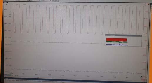
Time now to get out the PicoScope to scope the oxygen post sensor output to see what was happening and to gather technical data from a well-known information resource for this vehicle. I scoped the signal wire, sensor ground and heater current and saw the incorrect waveforms in Figure 1.
The signal wire was 1.5V, heater ground 14.7V and heater current 0A – something was not right here! I rechecked the technical data and the connection was correct, but something was very odd here. I had another wiring diagram from Ben Martins at Pico who kindly sent me technical data from a different resource. This was different to the previous wiring diagram, but which one was correct? Or were they both incorrect?
We must be so careful and vigilant to ensure we have the correct information to help us diagnose faults. This certainly is not the first time I have had problems with incorrect data from well-known resources, so we must be on our toes. All the years of experience and training does not prepare you for these problems, go by what you know and not what you do not know.
Well, it was time to get back to basics and get out my trusted test light and multimeter. I disconnected the sensor connector and probed the sensor connectors with my ohmmeter to identify the heater circuit, which was around 8Ω. I then connected my test light to battery positive to find the sensor signal earth wire – when the test light illuminated, I had found the earth wire.
I switched the ignition on and probed the harness side of the connector, still connected to battery positive, to find the heater earth wire. I then connected my test light to battery earth and one of the connector wires to find the heater feed, which was indicated by my test light illuminating.
The remaining wire in the connector now had to be the sensor signal wire, I then had enough information to work on. The technical information and wiring diagram from Ben Martins at Pico had the correct technical circuit information for my vehicle.
Now I could test the circuit knowing that I had the correct information. In Figure 2, you can see the results of my sensor connector wire tests.
Something was not right with this waveform. Had I accidently got my scope on AC, or had my amps clamp gone AWOL? I checked it again, connected another amps clamp and no, this was the signal captured and all wires were connected correctly.
The amps clamp was pulsing between negative and positive; the sensor output was 1.27V and then started switching for a few seconds before going back to 1.27V output. It was now time to check the integrity of the sensor and circuit before thinking of changing the lambda post sensor.
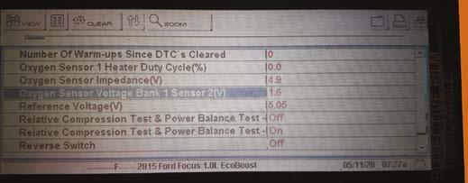
Figure 3
I sprayed carb cleaner into the inlet, and it did not make the sensor switch, but after a few sprays it slightly moved, but only once. A smoke test on the inlet found no visible evidence of an air leak, I also smoke checked the exhaust and could not see any leaks.
I decided to check the wires at the computer so I could be sure, and have proof, that the wiring going from the sensor to the computer was correct. I disconnected the battery earth cable terminal, removed the under-wing shield, headlamp, and tamper-proof screws on the ECU cover, then disconnected the ECU connector and protective cover to access the cable terminals.
I connected my power probe from the battery positive to each terminal – 1, 38 and 57, and connected a 21W bulb to the corresponding sensor connector terminals, and a good earth, one at a time. The light shone brightly on each connector terminal indicating good circuit integrity and there was no volt drop or resistance issues. I reconnected the ECU, headlamp battery terminal and under wing shield.
Before we went outside to sing, dance and do back flips, it was time to check that we had completed a correct diagnosis for this system. What other tests could I do before I replaced the lambda post sensor to be confident it was the sensor? I reconnected my scanner, disconnected the lambda sensor connector and checked the live reading on the PID for the lambda sensor output voltage to see if the computer was recognising a change and was working correctly.
With the connector disconnected a reading of 1600mV (1.6V) was seen on the scanner, see Figure 3. I then connected my test light to battery earth and probed the harness side of the connector of the signal wire, the reading on the scanner changed to 0V. This test proved signal circuit integrity from the connector all the way back to the computer.
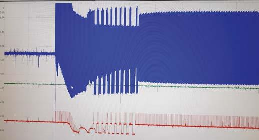
It was time to order and install a new lambda sensor 2. The heater circuit was now good after fitting a new sensor and I now could make the sensor switch. However, I did not like the post lambda switching, see Figure 4 & 5. It should be a straight line signal – there must be something wrong between the pre- and post-sensors.
The pre sensor, or sensor 1 on this vehicle system, was a wideband sensor and is more difficult to test. I used the scanner to check the PID and there was a current reading of -0.02mA, the minus indicates a slightly rich mixture.
Figure 4
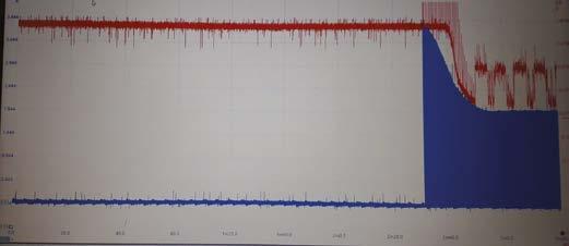
Figure 5
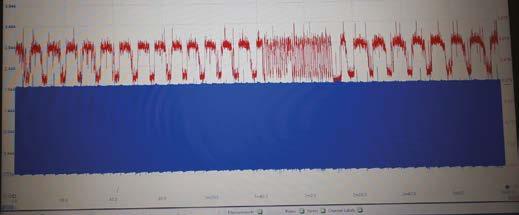
voltage output against the post sensor, or sensor2. But it is, what it is, and we have to adapt and apply our system knowledge, experience, training and the equipment available to the best of our ability to help us solve these problems.
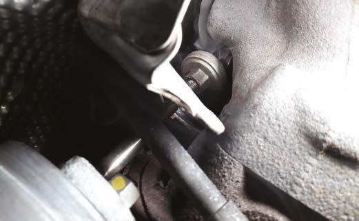
I removed the heat shields around the exhaust manifold and CAT and smoke tested the exhaust again to recheck. Bingo! The vehicle had an exhaust leak at the turbo waste gate mechanism at the turbo manifold. It needed a new turbo and a catalytic converter/manifold.
You could not easily see the small leak with the exhaust manifold heat shields fitted. Job done! One happy customer – well not really, especially after spending money changing all the parts – you certainly cannot satisfy everybody.
How important it is to get the correct information for the vehicle you are testing, to help you carry out the correct diagnosis. Otherwise, you can chase your tail and fit unnecessary parts and still not be able to fix the vehicle.
A special thanks to Ben Martins of Pico Technology for supplying me with the correct technical information for this vehicle.